This is the third of the five parts discussing the questions that I proposed and their solutions in the recently concluded 9th ASEP StructWhiz challenge.
1 Introduction
The one thing that is important in the structural engineering industry is to understand the Structural Code and apply it in the correct situations, so that we, structural engineers, can design structures that can withstand wind, earthquake, and other loads throughout their useful life, and hence are "durable for 10,000 years". This is actually one of the objectives of the ASEP StructWhiz Challenge.
In actual practice, we have lots of time to read the Code carefully, even do some research and consult our colleagues. But, what about in a structural engineering quiz bee, where time is limited?
In this article, I will give four examples, two of which I proposed in the 8th installment of the event, while the other two are from the 9th installment. The examples cover various degrees of difficulty, and along the way I will share some tips on how to read the Code provisions and tackle the problems depending on how much time you have. Hopefully, you will learn something from this article and be able to apply it in your next structural engineering quiz bees.
2 Tips
In my personal opinion, reading the Code in a time-constrained quiz bee usually requires six steps.
Step 1: Read the question. We want to know first what quantity we are to calculate. This will give us a targeted keyword when we start reading the Code in the next step.
Step 2: Skim through the Code provision. Look for the important words and phrases so that you will get a first idea of what the Code provision is about, and what formulas and variables are there. Do not read slowly at this point, as you do not have enough time to do that.
Step 3: Look for the main formula. Find the main formula based on what is required to solve in Step 1. Mark it in your questionnaire, or write it on a separate piece of paper.
Step 4: Look for the variables used in the formula in Step 3. We want to know what these variables are, if the values are given in the question or in the Code, or if the values have to be calculated using another formula. At this point, you can read the Code provision one more time. If it is given, list their values. If it is not given, then proceed to the next step.
Step 5: Repeat Steps 3 and 4. Do this until all variables we've found are either given in the problem, or given in the Code provision. By the end of this step, we also now have a working procedure of how to calculate the main formula.
Step 6: Start solving. Substitute them into the formulas in Step 5 to get the values of other variables, then finally substitute them all in the main formula in Step 3 to get the final answer.
You will see these six steps being applied in the following examples.
3 Example 1
from the 8th ASEP StructWhiz Challenge, Elimination Round, Easy (60 seconds)
Refer to the Code provision below.
NSCP 2015 Section 509.2.1.1.7
The nominal strength of one stud shear connector embedded in solid concrete is:
$$Q_n=0.5A_{sc}\sqrt{f'_c E_c} \leqslant A_{sc}F_u$$
where \(A_{sc}\) = cross-section area of stud shear connector, \(\text{mm}^2\), and \(F_u\) = specified minimum tensile strength of a stud shear connector, MPa.
Determine the nominal strength of a single 16-mm diameter shear stud connector embedded in a solid concrete encased composite column. The yield and ultimate strengths of the stud are 338 MPa and 420 MPa, respectively, while the 28-day concrete compressive strength is 20.7 MPa.
- 66.9 kN
- 84.4 kN
- 133.8 kN
- 142.7 kN
3.1 Solution
Step 1. We want to find the nominal strength of a single shear stud connector embedded in a solid concrete encased composite column.
Step 2. The Code provision only has one formula and four variables, so this question is actually straightforward.
Step 3. The main formula is
$$Q_n=0.5A_{sc}\sqrt{f'_c E_c} \leqslant A_{sc}F_u$$Step 4. The variables are
- \(A_{sc}\) = cross-section area of stud shear connector in \(\text{mm}^2\). Its value is not given.
- \(f'_c\) = 28-day compressive strength of concrete in MPa. Its value is given in the problem, \(f'_c\) = 20.7 MPa.
- \(E_c\) = modulus of elasticity of concrete in MPa. Its value is not given.
- \(F_u\) = tensile strength of the stud shear connector. Its value is given in the problem, \(F_u\) = 420 MPa.
Step 5. Let's look at the variables whose values we don't know yet. We have the formulas
- \(\displaystyle A_{sc} = \frac{\pi}{4}d_{sc}^2\), where
- \(d_{sc}\) = diameter of the stud in mm. Notice that its value is given in the question, \(d_{sc}\) = 16 mm.
- \(E_c = 4700 \sqrt{f'_c}\), where
- \(f'_c\) = 28-day compressive strength of concrete in MPa. Its value is given in the problem, \(f'_c\) = 20.7 MPa.
Notice that both of these formulas are not given in the Code provision. But an experienced quizzer already knows them at the back of their heads, since these are just standard formulas.
At this point, the Code provision is clear, and we can now solve the problem.
Step 6. We compute the intermediate variables first.
$$A_{sc} = \frac{\pi}{4}d_{sc}^2 = \frac{\pi}{4}(16)^2 = 201.0619\text{ mm}^2$$ $$E_c = 4700\sqrt{f'_c} = 4700 \sqrt{20.7}=21383.7088\text{ MPa}$$Then, once all intermediate variables are exhausted, we go to the main formula.
$$Q_n=0.5A_{sc}\sqrt{f'_c E_c} = 0.5(201.0619)\sqrt{(20.7)(21383.7088)} = 66884.6525\text{ N}$$ $$Q_n \leqslant A_{sc}F_u = (201.0619)(420)=84445.998\text{ N}\text{ (this is True)}$$Therefore, the answer is \(\boxed{Q_n = 66.9\text{ kN}}\). We choose letter \(\boxed{(a)}\). \(\square\)
4 Example 2
from the 9th ASEP StructWhiz Challenge, Elimination Round, Average (120 seconds)
Refer to the following code provision.
NSCP 2015 Chapter 5 Section A2.1
The roof system shall be considered stable for ponding and no further investigation is needed if both of the following two conditions are met:
$$C_p+0.9C_s\leqslant0.25\tag{1}$$ $$I_d\geqslant3940S^4\tag{2}$$where
- \(C_p=504L_s L_p^4/I_p\) = flexibility constant for the supporting beam
- \(C_s=504SL_s^4/I_s\) = flexibility constant for one-meter width of the roof deck
- \(L_p\) = column spacing in direction of girder (length of primary members), meters
- \(L_s\) = column spacing perpendicular to direction of girder (length of secondary members), meters
- \(S\) = spacing of secondary members, meters
- \(I_p\) = moment of inertia of primary members, mm4
- \(I_s\) = moment of inertia of secondary members, mm4
- \(I_d\) = moment of inertia of the steel deck supported on secondary members, mm4 per meter
For trusses and steel joists, the moment of inertia \(I_s\) shall be decreased 15% when used in the above equation. A steel deck shall be considered a secondary member when it is directly supported by the primary members.
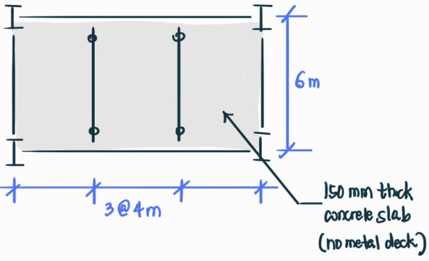
For the roof framing plan shown in the figure, if all beams have the same cross-section, calculate the minimum strong-axis moment of inertia of each of the beams so that the roof framing is considered stable for ponding.
- \(154 \times 10^6 \text{ mm}^4\)
- \(170 \times 10^6 \text{ mm}^4\)
- \(236 \times 10^6 \text{ mm}^4\)
- \(261 \times 10^6 \text{ mm}^4\)
4.1 Solution
Step 1. We want to find the strong-axis moment of inertia of each beam so that the roof framing is considered stable for ponding. Here, two terms are important:
- What is moment of inertia of the beam?
- What is considered stable for ponding?
Step 2. A scan of the Code provisions gives the answer to both questions.
- A roof system is considered stable for ponding if equations (1) and (2) are both satisfied. These are our main formulas.
- There are eight variables in the Code provisions. Three of these variables are about the moments of inertia of the beams.
Step 3. The main formulas are
$$C_p+0.9C_s\leqslant0.25\tag{1}$$ $$I_d\geqslant3940S^4\tag{2}$$Step 4. The variables in the main formulas are
- \(C_p=504L_s L_p^4/I_p\)
- \(C_s=504SL_s^4/I_s\)
- \(I_d\) = moment of inertia of the steel deck supported on secondary members, \(\text{mm}^4\) per meter. Its value is not explicitly given in the problem or the Code.
- \(S\) = spacing of secondary members, meters. It is given in the figure of the problem, \(S\) = 4 m.
Now, here's another tip. Always ask the question:
Do I need all the formulas and variables in the Code provisions?
To answer that question, we take a look again at the problem.
The problem asks for the moment of inertia of the beams. But, notice that \(I_d\) refers to the moment of inertia of the steel deck, the slab itself, and not of the beam. Also, notice that equation (2) uses \(I_d\) in the formula.
So, do we need these to solve the problem? The answer is no, and hence we can safely remove them from our notes.
Therefore, in Step 3, we are only left with one main formula:
$$C_p+0.9C_s\leqslant0.25\tag{1}$$And in Step 4, we are left with three variables:
- \(C_p=504L_s L_p^4/I_p\)
- \(C_s=504SL_s^4/I_s\)
- \(S\) = spacing of secondary members, meters. It is given in the figure of the problem, \(S\) = 4 m.
Step 5. We look at the variables whose values are not given. We have
- \(C_p=504L_s L_p^4/I_p\), where
- \(L_s\) = column spacing perpendicular to direction of girder (length of secondary members), meters. It is given in the figure, \(L_s\) = 6 m.
- \(L_p\) = column spacing in direction of girder (length of primary members), meters. It is given in the figure, \(L_p = 3\times 4\text{ m}\) = 12 m.
- \(I_p\) = moment of inertia of primary members, \(\text{mm}^4\). Its value is not explicitly given, because this is actually what we need to find.
- \(C_s=504SL_s^4/I_s\), where
- \(S\) = spacing of secondary members, meters. It is given in the figure of the problem, \(S\) = 4 m.
- \(L_s\) = column spacing perpendicular to direction of girder (length of secondary members), meters. It is given in the figure, \(L_s\) = 6 m.
- \(I_s\) = moment of inertia of secondary members, \(\text{mm}^4\). Its value is not explicitly given, because this is actually what we need to find.
Note that there is an additional condition in the question. All beams have the same cross-section. This means their moments of inertia will also be the same. The variables related to moments of inertia of beams are \(I_p\) and \(I_s\). Therefore, let
$$I_p = I_s := I_x$$where \(I_x\) is the moment of inertia that is being asked in the problem.
At this point, the procedure is now clear, and we can now start solving the problem.
Step 6. Starting with the intermediate variables, we have
$$C_p=\frac{504L_s L_p^4}{I_p}=\frac{504(6) (12)^4}{I_x}$$ $$C_s=\frac{504SL_s^4}{I_s}=\frac{504(4)(6)^4}{I_x}$$Now, we substitute this into the main formula to get
$$C_p + 0.9C_s = \frac{504(6) (12)^4}{I_x} + 0.9\cdot \frac{504(4)(6)^4}{I_x} \leqslant 0.25$$This is just a single inequality in a single variable, which we can solve manually:
$$I_x \geqslant \frac{504(6)(12)^4 + 0.9\cdot 504(4)(6)^4}{0.25}=260.2285\times 10^6 \text{ mm}^4$$Therefore, the minimum moment of inertia of the beams to skip checking for ponding stability is \(\boxed{261\times 10^6\text{ mm}^4}\). Choose letter \(\boxed{(d)}\). \(\square\)
5 Example 3
The previous two examples showed how to read Code provisions that are not being taught in a standard undergraduate structural engineering curriculum.
If a given Code provision is actually being taught in class, then the Code provision is only there as a reference just in case the participant forgot the formulas for some reason. An experienced quizzer should be able to skip some of the above steps in Code reading, or at least shorten them significantly. The next example will illustrate just that.
from the 9th ASEP StructWhiz Challenge, Elimination Round, Difficult (180 seconds)
Refer to the following code provision.
NSCP 2015 Section 507: Design of Members for Shear
§507.1: General Provisions.
Two methods of calculating shear strength are presented below. The method presented in Section 507.2 does not utilize the post buckling strength of the member (tension field action). The method presented in Section 507.3 utilizes tension field action.
The design shear strength, \(\phi_v V_n\), and the allowable shear strength, \(V_n/\Omega_v\), shall be determined as follows.
For all provisions in this section except Section 507.2.1(1)
$$\phi_v=0.90\,(\text{LRFD}),\,\,\,\,\,\,\,\,\,\,\,\, \Omega_v=1.67\, (\text{ASD})$$§507.2: Members with Unstiffened or Stiffened Webs
§507.2.1: Nominal Shear Strength
This section applies to webs of singly or doubly symmetric members and channels subject to shear in the plane of the web.
The nominal shear strength, \(V_n\), of unstiffened or stiffened webs, according to limit states of shear yielding and shear buckling, is
$$V_n=0.6F_y A_w C_v$$- For webs of rolled I-shaped members, with \(h/t_w \leqslant 2.24\sqrt{E/F_y}\),
$$\phi_v=1.00\,(\text{LRFD}),\,\,\,\,\,\,\,\,\,\,\,\, \Omega_v=1.50\, (\text{ASD})$$and
$$C_v=1.0$$- For webs of all other doubly symmetric shapes and singly symmetric shapes and channels, except round HSS, the web shear coefficient, \(C_v\), is determined as follows:
- For \(h/t_w \leqslant 1.10\sqrt{k_v E/F_y}\),
$$C_v=1.0$$ - For \(1.10\sqrt{k_v E/F_y} < h/t_w \leqslant 1.37 \sqrt{k_v E/F_y}\),
$$C_v=\frac{1.10\sqrt{k_v E/F_y}}{h/t_w}$$ - For \(h/t_w > 1.37\sqrt{k_v E/F_y}\),
$$C_v=\frac{1.51Ek_v}{(h/t_w)^2 F_y}$$
where \(A_w\) = the overall depth times the web thickness, \(dt_w\), \(\text{mm}^2\)
The web plate buckling coefficient, \(k_v\), is determined as follows:
- For unstiffened webs with \(h/t_w < 260\), \(k_v=5\), except for the stem of tee shapes where \(k_v=1.2\).
- For stiffened webs,
$$\begin{align*}k_v&=5+5/(a/h)^2 \\ k_v &= 5 \,\,\,\,\,\,\,\,\,\,\,\,\,\,\,\,\,\,\,\,\,\,\,\,\,\,\,\,\,\,\,\,\,\,\,\,\,\,\,\,\,\,\,\text{when }\frac{a}{h}>3.0\text{ or }\frac{a}{h}>\left(\frac{260}{h/t_w}\right)^2\end{align*}$$
where
- \(a\) = clear distance between transverse stiffeners, mm,
- \(h\) = for rolled shapes, the clear distance between flanges less the fillet or corner radii, mm,
= for built-up welded sections, the clear distance between flanges, mm,
= for built-up bolted sections, the distance between fastener lines, mm,
= for tees, the overall depth, mm
§507.2.2: Transverse Stiffeners
Transverse stiffeners are not required where \(h/t_w \leqslant 2.46\sqrt{E/F_y}\), or where the required shear strength is less than or equal to the available shear strength provided in accordance with Section 507.2.1 for \(k_v=5\).
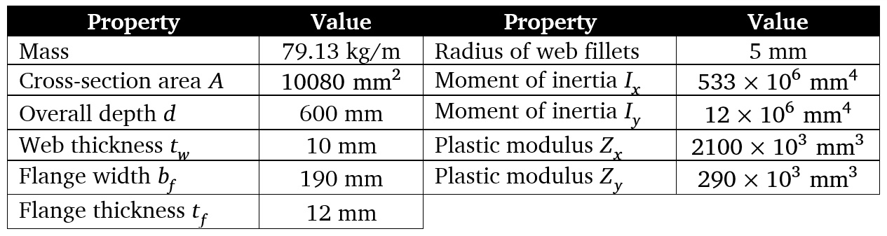
A BH600×79 wide-flange section that is made of ASTM A992 steel is to be used as a column for a four-story residential condominium project. The geometric properties of the column based on the 2004 ASEP Steel Handbook are given below.
Determine the ultimate major shear capacity of the column. Use LRFD provisions and ignore tension field action.
- 804 kN
- 1118 kN
- 1170 kN
- 1242 kN
5.1 Solution
Step 1. We want to find the major shear capacity of the BH600×79 column given its properties.
Step 2. There are lots of formulas and variables in the Code provision. But, we can see that there is only one main formula.
Step 3. The main formula is
$$\phi_v V_n=\phi_v\cdot 0.6F_y A_w C_v$$Steps 4 and 5. The variables in the main formula are
- \(F_y\) = yield strength of the steel column. Based on the problem, an ASTM A992 steel is to be used, which means \(F_y = 345\text{ MPa}\).
- \(A_w\) = the overall depth times the web thickness, \(dt_w\), \(\text{mm}^2\). Its value is not explicitly given, but we can calculate it.
- \(d\) = overall depth = 600 mm from the table,
- \(t_w\) = web thickness = 10 mm from the table,
Therefore,
$$A_w = dt_w=(600)(10)=6000\text{ mm}^2$$ - \(C_v\) = web shear coefficient factor. There are lots of formulas for calculating \(C_v\). However, notice that they are all classified based on the value of \(h/t_w\). So, we calculate this first.
- \(h\) = for rolled shapes, the clear distance between flanges less the fillet or corner radii, mm,
- The clear distance between flanges is equal to the overall depth minus the thicknesses of the flanges, \(d-t_f-t_f=d-2t_f\). Less the fillet or corner radii, which is \(-r_f-r_f=-2r_f\), so the overall formula is \(h = d-2t_f - 2r_f\).
- \(d\) = overall depth = 600 mm from the table,
- \(t_f\) = flange thickness = 12 mm from the table,
- \(r_f\) = radius of fillets = 5 mm from the table,
Therefore,
$$h = d - 2t_f - 2r_f=600-2(12)-2(5)=566\text{ mm}$$ - \(t_w\) = web thickness = 10 mm from the table.
Therefore,
$$\frac{h}{t_w}=\frac{566}{10}=56.6$$Now, we compare this to the thresholds item by item. First, Item 1 of Section 507.2.1 reads:
For webs of rolled I-shaped members, with \(h/t_w \leqslant 2.24\sqrt{E/F_y}\),
$$\phi_v=1.00\,(\text{LRFD}),\,\,\,\,\,\,\,\,\,\,\,\, \Omega_v=1.50\, (\text{ASD})$$and
$$C_v=1.0$$We have
- \(E\) = modulus of elasticity of steel = 200000 MPa.
- \(F_y\) = yield strength of the steel column, \(F_y = 345\text{ MPa}\).
Now, \(h/t_w=56.6 > 2.24\sqrt{E/F_y}\), so we move to the next item.
For webs of all other doubly symmetric shapes and singly symmetric shapes and channels, except round HSS, the web shear coefficient, \(C_v\), is determined as follows:
- For \(h/t_w \leqslant 1.10\sqrt{k_v E/F_y}\), \(C_v=1.0\)
- For \(1.10\sqrt{k_v E/F_y} < h/t_w \leqslant 1.37 \sqrt{k_v E/F_y}\), \(C_v=\frac{1.10\sqrt{k_v E/F_y}}{h/t_w}\)
- For \(h/t_w > 1.37\sqrt{k_v E/F_y}\), \(C_v=\frac{1.51Ek_v}{(h/t_w)^2 F_y}\)
A BH section is a built-up (welded) wide-flange section and is therefore not a rolled I-shaped member. Hence, this item applies.
We first determine \(k_v\):
- The column web is unstiffened,
- \(h/t_w = 56.6 < 260\),
Therefore,
$$k_v = 5$$Now, we compute the threshold:
$$1.10\sqrt\frac{k_v E}{F_y} = 1.10\sqrt\frac{5(200000)}{345} = 59.2212$$Since \(h/t_w = 56.6\) is less than this threshold, we fall under the first case:
$$C_v = 1.0$$We also check: since the first item does not apply, the \(\phi_v\) factor defaults to the general provision:
$$\phi_v = 0.90$$ - \(h\) = for rolled shapes, the clear distance between flanges less the fillet or corner radii, mm,
Step 6. Now we have all the variables needed for the main formula. Since all intermediate variables are already determined, we go directly to the main formula.
$$\phi_v V_n = \phi_v \cdot 0.6 F_y A_w C_v = (0.90)(0.6)(345)(6000)(1.0) = 1\,117\,800\text{ N}$$ $$\boxed{\phi_v V_n = 1118\text{ kN}}$$Therefore, we choose letter \(\boxed{(b)}\). \(\square\)
Comments
Loading comments…